EECS 31L | EX-802 | Processor Design II

Control Signals

Document version: v0.1a
Last modified: 2026-05-28 22:12
Canvas: [ EECS 31L Workspace ]
You will need access to RISC-V ISA. You only need the first page.
Datapath diagram
Part A: Decode and Control

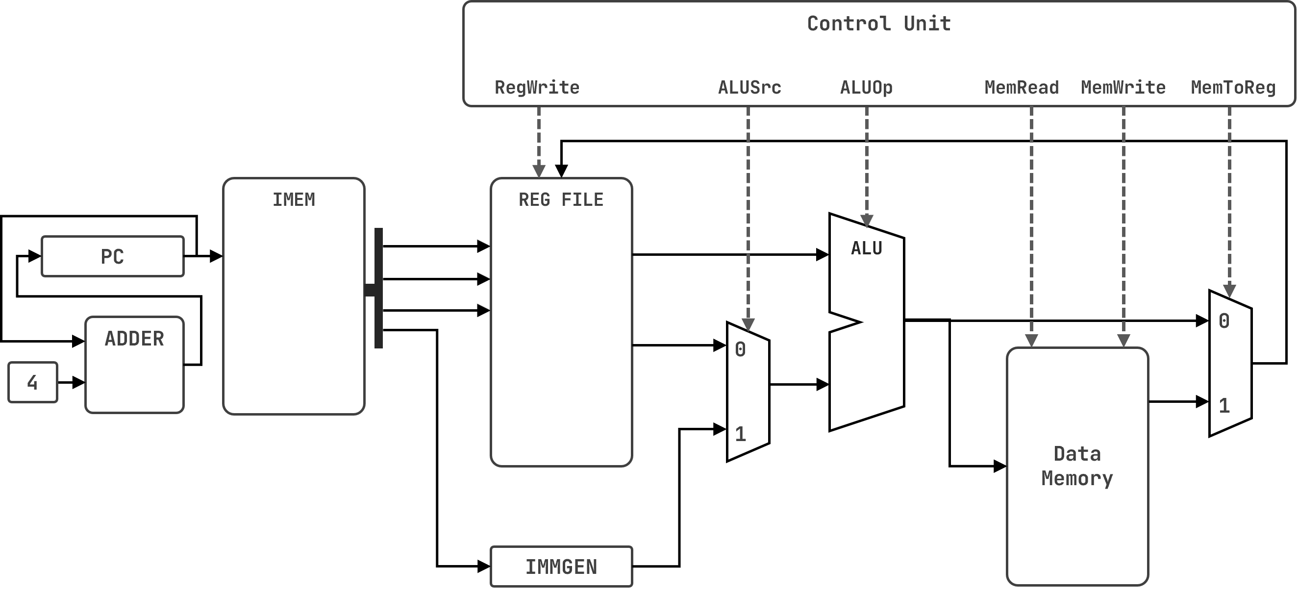
You are given a 32-bit single-cycle RISC-V processor with the datapath shown above.
Q1: Decode and determine the control signals for: 0x002081B3

Step 1: Convert to binary.
0x002081B3 =   

Step 2: Identify the fields. Write none if the field is not used.
Opcode:   funct3:   funct7:

Step 3: Identify the instruction.
Type:   Mnemonic:

Step 4: Determine the control signals.
reg_write:   alu_src:   mem_read:   mem_write:   mem2reg:
💡 HintFrom RISC-V ISA document, lookup which bits correspond to the opcode and use it to determine the instruction type. Then use the ISA table to interpret the funct3. If there is a funct7 field, use it as well. Once you have the instruction, ask yourself:
- does this instruction have a destination register?
- does this instruction use an immediate value?
- does this instruction read from memory?
- does this instruction save a value to memory?
- does this instruction load a value from memory to write it back to a register?
The answer to each question determines the value of a control signal. However, always consult the datapath diagram when it comes to MUX control/select signals.
Q2: Decode and determine the control signals for: 0x00F46413

Step 1: Convert to binary.
0x00F46413 =   

Step 2: Identify the fields. Write none if the field is not used.
Opcode:   funct3:   funct7:

Step 3: Identify the instruction.
Type:   Mnemonic:

Step 4: Determine the control signals.
reg_write:   alu_src:   mem_read:   mem_write:   mem2reg:
💡 HintFrom RISC-V ISA document, lookup which bits correspond to the opcode and use it to determine the instruction type. Then use the ISA table to interpret the funct3. If there is a funct7 field, use it as well. Once you have the instruction, ask yourself:
- does this instruction have a destination register?
- does this instruction use an immediate value?
- does this instruction read from memory?
- does this instruction save a value to memory?
- does this instruction load a value from memory to write it back to a register?
The answer to each question determines the value of a control signal. However, always consult the datapath diagram when it comes to MUX control/select signals.
Q3: Decode and determine the control signals for: 0x00B42623

Step 1: Convert to binary.
0x00B42623 =   

Step 2: Identify the fields. Write none if the field is not used.
Opcode:   funct3:   funct7:

Step 3: Identify the instruction.
Type:   Mnemonic:

Step 4: Determine the control signals.
reg_write:   alu_src:   mem_read:   mem_write:   mem2reg:
💡 HintFrom RISC-V ISA document, lookup which bits correspond to the opcode and use it to determine the instruction type. Then use the ISA table to interpret the funct3. If there is a funct7 field, use it as well. Once you have the instruction, ask yourself:
- does this instruction have a destination register?
- does this instruction use an immediate value?
- does this instruction read from memory?
- does this instruction save a value to memory?
- does this instruction load a value from memory to write it back to a register?
The answer to each question determines the value of a control signal. However, always consult the datapath diagram when it comes to MUX control/select signals.